

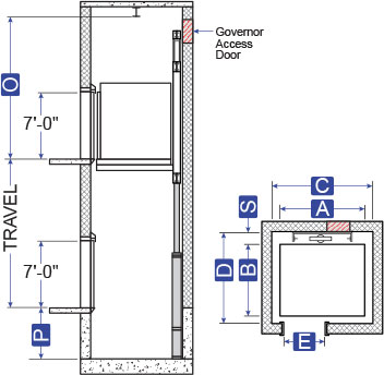
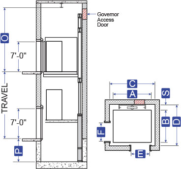
A = Platform Width
B = Platform Depth
C = Hoistway Width
D = Hoistway Depth
E = Clear Door Opening
O = Overhead
P = Pit Depth
S = Platform to Wall

Download Available Information
Contact an Elevator Package Representative to place an order
Application Summary
This is a holeless design limited to low capacity applications. Wire ropes are utilized in conjunction with a hydraulic jack to lift the car at a 1:2 ratio. For every foot that the jack rises, the car rises two feet. The jack and rail equipment is mounted either to the side or to the rear of the car, depending upon the opening configuration.
Advantages
- No jack hole is required even though the travel can be as great as 100 feet. Without a jack in the ground, the risk of oil contamination is eliminated.
- Front & side openings can be easily accommodated.
- No extensive pit or overhead is required.
Code year adoptions and local code variations may affect the hoistway size. Verify all dimensions with MEI prior to construction.
ENGINEERED TO ORDER – Contact MEI For Sizes or Capacities Outside Listed Ranges
Specifications
Passenger Elevators – Standard Specifications (Low Capacity)
Capacity (lbs)
Platform
A x B
A x B
Hoistway
C x D
C x D
Front/Rear
Laminate Clear Inside W x D
Door Type
Door Width E
Side Door Type
Side Door Width F
Elevation & Plan View Drawings
2100 Lbs
6′ -0″ x 5′ -1″
7′ -4″ x 7′ -3 1/4“
F
5′ -9″ x 4′ -3 1/2“
1-SP
3′ -0″
–
–
2100 Lbs
6’-5 1⁄2” x 5’-1 1⁄4”
7’-8” x 7’-3 1⁄2”
F/S
5’-9” x 4’-3 1⁄2”
1-SP
3′ -0″
2-SP
3′ -0″
2500 Lbs
7′ -0″ x 5′ -1″
8′ -4″ x 7′ -3 1/4“
F
6′ -9″ x 4′ -3 1/2“
1-SP
3′ -6″
–
–
2500 Lbs
7’-5 1⁄2” x 5’-1 1⁄4”
8’-8” x 7’-3 1⁄2”
F/S
6’-9” x 4’-3 1⁄2”
1-SP
3′ -6″
2-SP
3′ -6″
3000 Lbs
7′ -0″ x 5′ -6″
8′ -4″ x 7′ -8 1/4“
F
6′ -9″ x 4′ -8 1/2“
1-SP
3′ -6″
–
–
3000 Lbs
7’-5 1⁄2” x 5’-6 1⁄4”
8’-8” x 7’-8 1⁄2”
F/S
6’-9” x 4’-8 1⁄2”
1-SP
3′ -6″
2-SP
3′ -6″
3500 Lbs
7′ -0″ x 6′ -2″
8′ -4″ x 8′ -4 1/4“
F
6′ -9″ x 5′ -4 1/2“
1-SP
3′ -6″
–
–
3500 Lbs
7’-5 1⁄2” x 6’-2 1⁄4”
8’-8” x 8’-4 1⁄2”
F/S
6’-9” x 5’-4 1⁄2”
1-SP
3′ -6″
2-SP
3′ -6″
4000 Lbs
8′ -0″ x 6′ -2″
9′ -4″ x 8′ -5 3/4“
F
7′ -9″ x 5′ -3″
2-SP
4′ -0″
–
–
4000 Lbs
8’-5 1⁄2” x 6’-0 3⁄4”
9’-8” x 8’-3”
F/S
7’-9” x 5’-3”
1-SP
4′ -0″
2-SP
4′ -0″
P Pit Depth = 4′ -0″ • O Minimum Overhead = 12′ -5″ • Cab Height = 8′ -0″ • S Platform to Wall = 20″